You are currently viewing Atari Joystick

Atari Joystick

The Atari joystick is a controlled device that can be used to manipulate raster dots on the screen that move objects. Essentially these were made popular ever since the first Atari Pong game launched in the early 70’s. Much later Atari incorporated simple joysticks on their arcades, and the Atari 2600 made them extremely popular. You can also check out the History of Atari page to learn more about the company.

Potentiometer Control

Atari hardware

Before we dab into writing some fun joystick routines, let’s explore the hardware first. It’s important to break it down to be sure that it is understood at the lowest level.

Deep inside your Atari joystick is a potentiometer that controls the direction of movement aided by wires that connect to the tiny ports at the end of the plugs. Here is a simple screenshot of a potenometer from my own electronics supply. When you turn the dial it sends electric current to the hardware device once it has received voltage from a battery or alternate power source plugged into the Atari 65xe computer or similar 8-bit systems. The computer software then translates this as bits to tell which direction the controller has moved into.

Listed here is a photograph of the Atari joystick’s internal board. Observe the wires that connect to the board. When the joystick is moved the plastic under the stick presses against the board where it makes contact and sends current through the path on the circuit board which translates information to the connected wires leading to the pin outs at the base.

In return, the fire button emulates the same thing when the button pressure is applied against the metal contact on the circuit board.

After contact is made on the board this closes the circuit and passes electricity to the wires and sends information back to the memory addresses for the Atari joystick.

This is considered a mini controller and is used in devices like radio, television knobs, and a lot more. It doesn’t exactly emulate a joystick, but is the best example I could come up with before taking apart an Atari joystick. If this were a lesson on Atari paddles, it would be perfect though.

Atari joystick

It’s probably also important to mention that there a quite a large number of joystick types available on the Internet. I own several already and will focus on one of favorites. First let’s take a ride down memory lane.

After Atari Incorporated created the Atari VCS game system, the Atari joystick became quite familiar with the community and the customers who purchased the console. An Atari joystick is surrounded by a plastic case. It has a stick control in the center that manages movement, such as up, down, left, right, and in the diagonal directions. There is also one red button on the controller.  The joystick can move a character around on a display and the button is known as the “fire button”. This is because in the early arcades a button was used to fire a weapon at an oncoming enemy.

In order to control a character on a screen display, the computer must first recognize which direction you have moved the joystick in. Inside the Atari computer’s memory, a register manages this information and it can read output to the port on your Atari computer, sending electrical impulses to the joystick when it is plugged in (recall the potentiometer  example earlier). Let’s explore further.

Atari Joystick Register Values

Atari joystick registers

Mapping the Atari
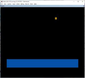
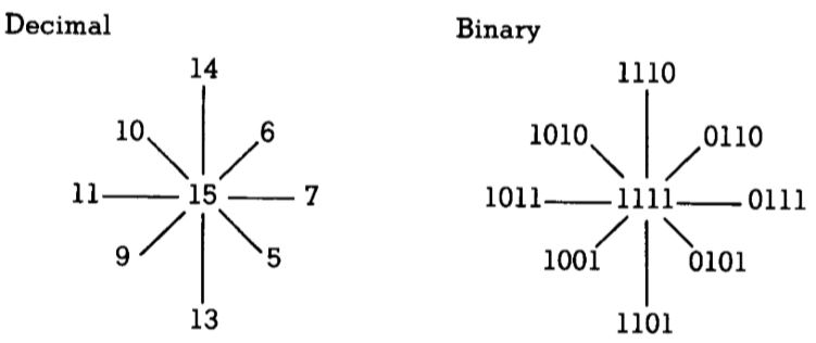
In the Compute! book Mapping the Atari, memory register 632 receives the current from the joystick and records it here for use. The register is called STICK0, and these registers range from STICK0 – STICK3 (632-635). The book also states that “STICK registers are shadow locations for PIA locations 54016 and 50417 ($D300, $D301). It contains up to 9 values that are read, based on which way the joystick is moved.

Now let’s examine a diagram to get more information. Look at the screenshots below. You will see the values that are found in the appropriate direction the joystick is facing. The binary chart shows how it is read by the 6502 chip. 

Atari Joystick Value Display

Joystick value display

Finally let’s see this in action. For our first program, we are going to just create a simple loop to display the values on the Atari screen.

10 PRINT PEEK(632)
20 GOTO 10

So for our simple exercise, be sure you have plugged a joystick into port #1 or if you are using the Atari Altirra emulator, you can use an Xbox controller, or something similar to try this test.

By default when you are not moving the joystick (known as the “idle” position), the Atari outputs a 15 to memory location 632 from our program. Now try moving the joystick in various directions and you will see the other values from the chart above on your screen. For example moving up will show a 14.

Now let’s create a more interesting program. Instead of showing values on the screen, we are going to use conditional statements to read the direction a joystick is moved in and print messages on the screen. This is how our future games will be managed as well. 

Type in the program below and RUN it afterward. You will be greeted by a screen with nothing going on yet. Now move the joystick in any direction and messages will start to appear for the way you are moving in.

Atari Joystick Movement

We also introduced a new command here called STICK(0). That command will do the same thing as reading PEEK(632) and is common in many Atari Basic games and programs.

10 REM JOYSTICK MESSAGES
20 ST=STICK(0)
30 IF ST=14 THEN PRINT “MOVING UP”
40 IF ST=13 THEN PRINT “MOVING DOWN”
50 IF ST=11 THEN PRINT “MOVING LEFT”
60 IF ST=7 THEN PRINT “MOVING RIGHT”
70 GOTO 20

Let me explain further how the program works.

Line 20 is reading the input values of the joystick

Lines 30-60 are reading the joystick values based on which direction the joystick was pushed in to reflect the values found in memory locations 632.

Line 70 returns to line 20 to stay in a loop and continue to wait for the user to move the joystick.

Atari Joystick Fire Button

In the last part of this tutorial, be sure to add the new lines below to send a command to the button on the joystick when it is pressed.  You could also use TR=PEEK(644) to accomplish the same thing on line 25.

Joystick fire button

10 REM JOYSTICK MESSAGES
20 ST=STICK(0)
25 TR=STRIG(0)
30 IF ST=14 THEN PRINT “MOVING UP”
40 IF ST=13 THEN PRINT “MOVING DOWN”
50 IF ST=11 THEN PRINT “MOVING LEFT”
60 IF ST=7 THEN PRINT “MOVING RIGHT”
70 IF TR<1 THEN PRINT “FIRE BUTTON IS PRESSED”
80 GOTO 20

A quick explanation of the new lines. 

Line 25 – reads the joystick button when being pressed

Line 70 – if the joystick variable value of TR is less than 1 (means its equal to zero), then the fire button was pressed. So show the message.

In this lesson you learned about some joystick hardware, how to display joystick values on the screen, how to read the fire button being pressed, and show actions from conditional statements when the joystick is moved. 

As a challenge, see if you can upgrade this program. Try something like displaying an ASCII character on the screen. See if you can make it move. Hint: Use PRINT CHR$(125) to clear the screen each time.

Much later we will explore ASCII character movement, animation, and eventually Player Missile Graphics animation. Be sure to check out my page Atari Player Missile Graphics to see an example.

I hope this lesson was informative and simple enough. Please be sure to bookmark this page for your records as there is yet even more exciting things to come soon!

Please follow and like us:

smorrowatari

Steve has always had a passion for computers even before I owned one. His first personal computer was an Atari 65xe purchased at Children's Palace around 1986. In later years he attended DeVry University and received a Computer Science degree, works as a Front End Web Developer and is a born again Christian. Although this is a tech site, I am never shy to admit that I am a sinner saved by the blood of Jesus Christ. If you ever want to talk about salvation, I'm game.